Stopped tweaking and started measuring. I wrote an automated test suite that checks whether the integrator computes the right buoyant force, whether the corrected torque formula settles at the analytical equilibrium, and whether the adaptive clipping path gives different results than the linear one.
the test harness
I wrote a Unity MonoBehaviour called AccuracyTests that runs each test as a coroutine. For the static tests (force sweep, equilibrium tilt), it freezes the rigidbody, teleports it to a known position, waits for physics to tick, then reads the force/torque from the DLL via reflection. Everything outputs CSV-formatted [TEST] lines to the Unity console.
One gotcha, when the rigidbody is set to kinematic for the static sweep, Unity zeroes out the inertia tensor for constrained axes. The BuoyancyController divides angular momentum by inertia to get angular velocity, division by zero -> NaN -> Unity screams. Fixed with a simple guard: skip the division if the tensor component is below 1e-6f.
force sweep, cube submersion
The simplest possible validation. A 1×1×1 cube, flat water (all wave steepnesses set to 0), swept from 0.6m above to 0.6m below the surface in 25 steps. At each step, compare the DLL's computed force against the analytical .
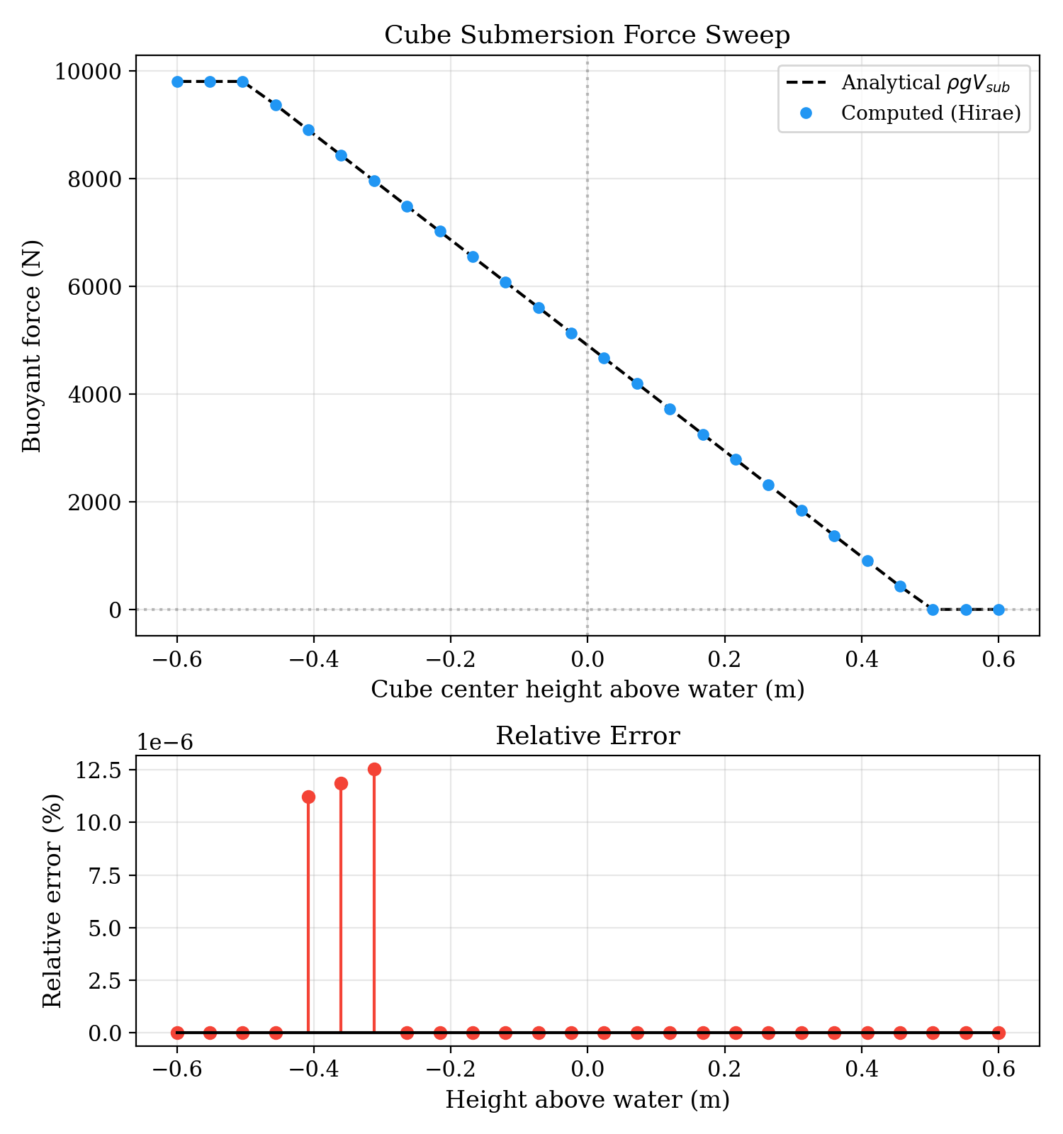
The top panel shows computed vs analytical force, they are literally on top of each other. The right panel shows relative error on a 1e-6 % scale. That's 32-bit floating point noise. The integrator is exact to machine precision on flat water, which makes sense, the closed-form equations were derived for a linear water surface, and flat water is the simplest case of that.
equilibrium tilt, corrected vs paper formula
This is the test that matters most. A 1m³ cube with density ratio 0.75, constrained to rotate around one axis only (matching the 2D-bar setup in Hirae et al. Table 1). Drop it with a 5° initial tilt, let it settle, read the equilibrium angle.
The analytical answer is . The corrected formula settles to 26.565° with a residual torque of 2.4×10⁻⁵ N·m, in essence zero. The paper's printed Eqs. 7–9 settle to 45.000° with a permanent residual torque of 215.9 N·m. The cube reaches force equilibrium () but the torque never vanishes because the auxiliary vector is wrong.
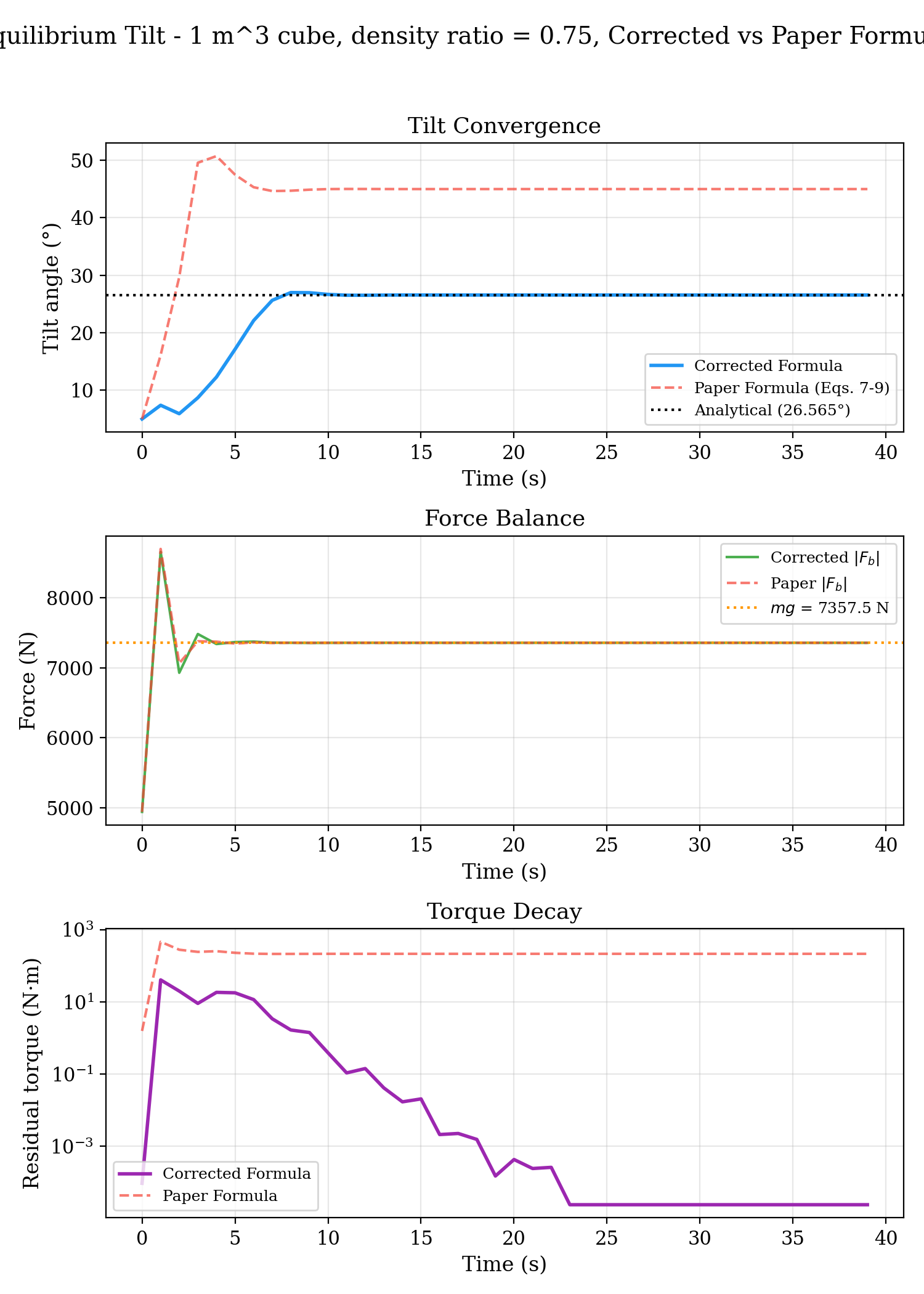
Top panel is tilt, the corrected formula converges to the analytical 26.565° and the paper formula overshoots and sticks at 45°. Middle is force, both reach equilibrium at N, so the force equation (Eq. 5) is correct in both versions and the typo is only in the torque (Eqs. 7/9). Bottom is torque, the corrected one drops 6 orders of magnitude to ~10⁻⁵ and the paper one flatlines at 215 N·m.
This is the plot going into the bug report I will send to the authors. The factor-of-2 error in the and components of the auxiliary vector doesn't affect the force at all (force uses a different equation), but it produces a constant rotational bias that prevents correct equilibrium.
adaptive vs linear clipping, convergence vs dense ground truth
Adaptive clipping produces different results than linear clipping, that much I knew. The question is if they are better.
That needs a ground truth. There is no analytical solution for a bunny floating on Gerstner waves, but a 30,000-triangle mesh through the pure linear integrator gets close enough. The triangles are small relative to the wave period, so the linear chord across each one barely differs from the local water curve. I treat the 30k bunny as the ground truth.
I dropped three identical 250-triangle bunnies into the same rough waves alongside the 30k bunny, one on the linear path, one on the adaptive path with N=4 and one with N=16.
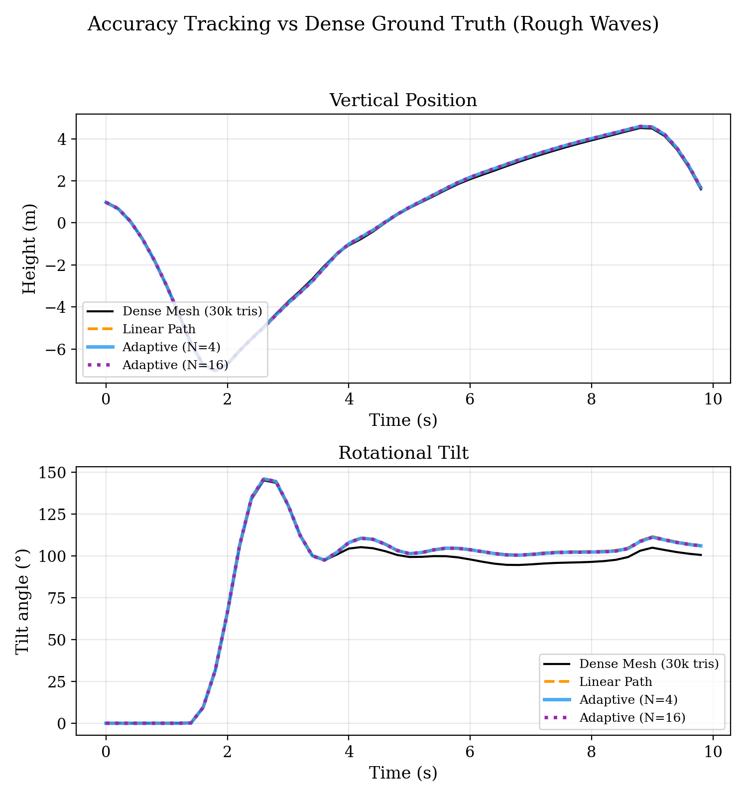
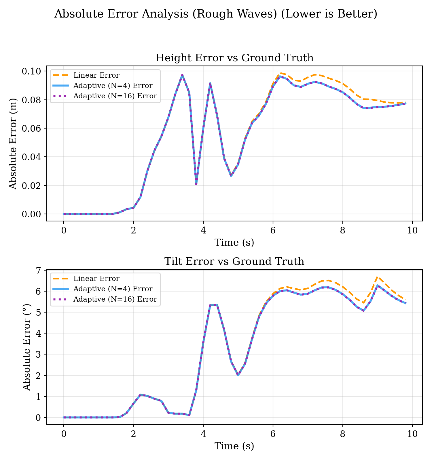
Up to about the three error lines are on top of each other. After that, once the bunnies are fully in the waves, the linear path drifts up to ~6.5° of tilt error and ~10 cm of height error, and the adaptive paths sit slightly below it, by maybe 0.5° at the peaks and under a centimetre of height. Both are still around 6° off the ground truth, so the gap between them is small next to the error they share.
The N=4 and N=16 lines lie on top of each other, I can't tell them apart. is converged for this mesh, calculating 16 points along the waterline adds nothing.
The remaining ~6° against the ground truth is not a clipping error. A 250-triangle bunny has big flat polygons where the 30k bunny has curves (ears, paws), so the algorithm is computing the curved waterline across a blocky volume. That 6° is the volume error of the low-poly mesh, and clipping alone cannot fix it.
does it matter for a game
Adaptive clipping works and converges, so the next question is what it costs. In the stress test, computing the adaptive curve across 100 bobbing objects means over 12 million trigonometric function calls per second, and because the sub-triangulation relies on dynamic arrays it had to be written in standard C# rather than Burst. That drops frame rate from 300+ FPS on the linear path to single digits on the adaptive one, numbers in the evaluation post.
So, adaptive clipping converges at N=4, and the gain over linear is under 1° of tilt while the mesh volume error is about 6°. The adaptive path also costs far more per frame. The linear DLL is what the game uses.